Interfacing a graphic LCD
A few years ago, I purchased a surplus set-top box that was basically just a generic 100Mhz x486 compatible computer that I was going to use as a component in my stereo system to play MP3s, complete with remote and LCD display. I wrote the server-side database (Apache, SQL) and had most of the client-side software written (all in Perl, IIRC.) The last piece of the puzzle was getting the LCD & remote (plus a rotary encoder for good measure) working. I had already found the perfect LCD (from All Electronics, of course); it was the (almost) perfect physical dimensions for my box, and I had already designed some variable-width fonts and planned the functionality of the interface - I just, you know, didn't know how to make it all work. Well, I decided to tackle this last part of functionality.
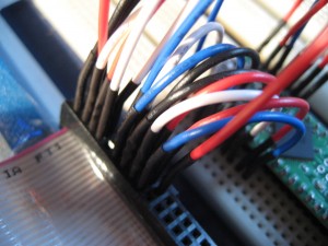
I had saved this project for later, reasoning that it would be the most challenging. It turned out to be pretty simple (the TS6963 controller IC is pretty easy to interface with), and most of the work I had was in learning some intricacies of GCC with the AVR, and how to store/access data within the flash memory. The first hurdle to overcome was wiring-up the display module. It used a 2x20 header pin, which is not realy compatible with a standard breadboard. I was, however, able to overcome this using some flexible jumpers. The specification for the display also called for a ~-6v input, so I had to do my prototyping on a different breadboard that had a -12V output and a 10k variable resistor.
In poking around online for information on interfacing with the controller, I stumbled upon some source code for Atmel MCUs. With just a few modifications to the header files to adjust for my particular configuration, the code worked the first time.
-- To be continued
