Tutorial Project: External System Gauge (Part 1)
 I think a tutorial is best served by working through a functional example. For our first one, we are going to use the Teensy to receive real-time system parameters (CPU utilization/temperature, memory usage) via a USB connection and display them using an analog meter (specifically, the one shown to the left.)
The Equipment
Since this is the first tutorial, I am going to provide links to all the components that we will need to make this happen. It seems like a big order, but most of the components will be used throughout all of the tutorials. Additionally, everything (aside from the Teensy) can be ordered from All Electronics to minimize shipping costs.
 For this project, you will need the following (all prices are as of Mar. 13th, 2011):
- Teensy++ w/ pins ($27.00)
- 1680 contact solderless Breadboard ($15.95)
- 350 piece jumper wire assortment ($12.95)
- 610 1/4W resistor assortment ($11.50)
- 14 Pin straight header x 4 ($0.25 x 4 = $1.00)
- 4 Pin connector with header ($1.30)
SPST momentary N.O. pushbutton ($0.60)These don't have standard DIP headers- 4 LED Stack, Bi-color (3 for $1.00)
- 0-50MV Ammeter ($10.00)
That is a total of $83.48 for everything, not including shipping. Like I said previously, it seems a tad bit high, but most of the components can be reused for other tutorials. Now, for a little more information on each item on that list.
Teensy 2.0++
The Teensy is at the heart of our projects. It contains a 16MHZ AVR AT90USB1286 CPU placed onto a 46 pin DIP package. It has 128K of flash memory for program storage, 8K of RAM and 4K of EEPROM storage. It also has 46 I/O lines include 9 PWM (Pulse Width Modulation) generators and 8 10-bit ADCs (Analog to Digital Converters.) What makes the teensy most attractive, however, is the on-board USB connection. Connected to a computer via USB and using a pre-programmed custom bootloader, getting our code onto the Teensy is as easy as running a driver on the computer and pressing a button on the Teensy. It's an excellent arrangement for those just getting their feet wet. From the PJRC website:
The Teensy Loader makes getting code into your Teensy easy. Just press and release the reboot button and the processor runs the HalfKay bootloader, which is automatically detected. Teensy Loader lets you download your code and reboot to it.
Automatic mode downloads and reboots to your code the instant your computer detects HalfKay. The latest version of your code is always used. Just press the button and within 1 to 2 seconds your latest code is running!
It really is that simple. For those that don't need a full blown in-line debugger, it offers a pretty seamless development environment.
Breadboard, Jumper wires, resistors, headers
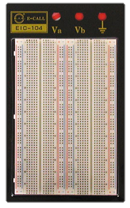
 If the Teensy is the heart, then these parts make up the circulatory system. The breadboard is the support for our components and allows us to easily interface them to the Teensy. The breadboard is composed of two separate sections: the terminal strip and the bus strip (see diagram below.) Each bus strip is composed of two columns of connected contact points and is generally used for power and ground (the red and blue stripes, respectively.) The terminal strip is made up of conne
cted rows of contact points and is used to connect the components to each other. In our projects, the Teensy will be positioned over the grey center area, giving us a separate bus row for each pin of the Teensy. Other components, such as buttons and LEDs will similarly occupy as many rows as they have electrical connections.
The jumper wires are what are used to connect one row to another row, or a row to a bus strip column. This is the way we will connect our components together on our breadboard.
Headers are merely collections of pins held together with a plastic substrate and are designed to mate with the spacing of the breadboard. The are useful for connecting components that will not fit onto the breadboard, interfacing multiple breadboards or for situations where the connections are too dense to use standard jumper wires (an 8-bit data bus is an example of this - using a piece of ribbon cable is much cleaner.)
Resistors are excellent to have around. Since we will be interfacing components directly with our Teensy, we want to make sure we aren't drawing too much current through it, possibly causing a short circuit or, worse, killing it! Resistors will serve in this capacity.

4 pin connector, pushbutton, 4 LED Stack
We are going to use the pushbutton and the 4 LED Stack for control/feedback within our system. You will find using LEDs in your circuit tool is an effective method of debugging in those times your code has you scratching your head. We are going to use the 4 of them to indicate various process points (successful USB connection, data acquisition, etc.) The 4 pin connector (along with the headers mentioned above) will be used to connect to the Ammeter.
Ammeter
This is the centerpiece of our tutorial. Essentially, what we want to do is use our digital device to create an electrical environment for this analog meter so that we can display our information. This is the one part of the project that I am not entirely confident about - I could not find enough information on either All Electronics nor the manufacturer website to determine if we will be able to successfully use this component. I am pretty sure we will be able to drive it using PWM (Pulse Width Modulation) and a simple RC Filter circuit (or even just a resistor!) I won't know more until my order from All Electronics is delivered later this week.
Next time, I will cover what needs to be done to install the development environment. I had planned to cover this first, but Apple has made some changes to Xcode (for one, it's no longer free... :/) and I need to explore that somewhat before I can get a tutorial put up.